
Metal C Rings
Metal C-rings are precision-formed metal seals with a C-shaped cross-section, used where elastomer seals can’t survive the temperature, pressure or chemical environment. The open side of the C acts like a spring, flexing under compression and pushing back, often utilising system pressure, against the flange faces to maintain a seal. This page explains how metal C-rings and metal C-seals work, the difference between open and spring-energised versions, where they’re used, and what to think about when specifying one.
What is a metal C-ring?
A metal C-ring is formed from a thin-walled metal ribbon, formed into a C-shaped profile. When the ring is compressed between two flange faces, the C shape deflects slightly and tries to spring back to its original form, often assisted by system pressure. That spring-back is what generates the sealing contact force at both the inside and outside diameters of the groove.
C-rings vs spring-energised C-seals
A C-ring relies on the spring-back of the formed metal jacket itself and system pressure. It’s simple, cost-effective, and suitable for applications where the compression set and thermal movement are modest.
A spring-energised C-seal adds a helical spring inside the C cross-section. The spring supplements the jacket’s own spring-back, giving:
- A more consistent sealing load across a wider range of flange movement and surface imperfection
- Better recovery after thermal cycling, where the flange gap can open and close repeatedly
- Lower sensitivity to relaxation of the jacket material at sustained high temperature
The trade-off is a slightly more complex (and typically more expensive) seal, so spring-energised versions tend to be specified where the duty cycle, pressure fluctuation or flange movement would be too demanding for a C-ring.
Internal, external and axial pressure variants
How a C-ring is orientated in the groove matters as much as the material it’s made from. The opening of the C should generally face the direction the pressure is coming from, so the system pressure helps push the legs of the C outward against the sealing faces, adding to the mechanical spring force rather than working against it.
- Internal pressure (pressure-assisted outward): the C opens towards the bore, so pressure inside the vessel or pipe helps energise the seal against the groove walls.
- External pressure (pressure-assisted inward): the C opens outward, used where the pressure source is on the outside of the sealed joint.
- Axial variants: the ring is orientated to resist pressure acting along the axis of the joint.
Getting this orientation wrong doesn’t just lose the benefit of pressure assistance — in a hard vacuum or high-pressure differential, it can mean the joint doesn’t seal at all, so it’s worth confirming the pressure direction before finalising groove drawings.
Materials, plating and coatings
Metal C-rings are generally formed from corrosion-resistant and high-temperature alloys, with the choice driven by the chemical environment, operating temperature and the need (or otherwise) to match the thermal expansion of the flange material.
Platings and coatings are commonly applied to the outer surface to improve sealing at lower bolt loads, protect against galling, or add corrosion resistance beyond that of the base alloy — for example silver, gold, PTFE or nickel-based platings.
Typical applications
Metal C-rings and C-seals are specified wherever elastomer seals would fail from heat, pressure, chemical attack or radiation. Common application areas across industry include:
- Aero engine casings and ducting, where weight and bolt load are both constrained
- High-pressure and high-temperature valves
- Exhaust system joints exposed to thermal cycling
- Pressure transducers and instrumentation fittings, where a compact, low-profile seal is needed
Groove and compression design guidance
A C-ring only performs to its design intent if the groove is right. As a general principle:
- The groove depth and width need to achieve the correct percentage compression of the ring’s free height — too little and the seal won’t energise properly, too much and the jacket can over-stress or crack.
- Surface finish on the flange faces affects how well the seal can accommodate minor imperfections.
- Bolt load has to be sufficient to reach the required compression at every bolt position, which is particularly important on large-diameter or non-circular flanges where load can vary around the joint.
- Thermal expansion of the flange material relative to the seal should be considered where the joint operates across a wide temperature range.
Because these figures are specific to each seal diameter, section and material, it’s worth sending us your flange drawing or application details so we can confirm groove dimensions and compression for your particular case — see our static seals and spring-energised seals ranges for related profiles.
How to choose the right metal seal
When specifying between a static C-ring, a spring-energised C-seal, an O-ring or an E-seal, work through:
- Direction and magnitude of the pressure the seal has to resist
- Operating temperature range and how much the flange gap will move with thermal cycling
- Available bolt load and flange material
- Chemical compatibility of the base alloy and any plating
- Space available for the seal cross-section and groove
- Number of pressure/thermal cycles expected over the seal’s life
If you’re not sure which combination fits your application, send us the flange drawing, pressures and temperatures and we’ll work through the options with you.
Frequently asked questions
What’s the difference between a metal C-ring and a metal O-ring?
A C-ring has an open, hollow cross-section that flexes under compression, so it needs a lower seating load than a metal O-ring. An O-ring gives excellent leak-tightness but needs more bolt load to compress.
Do I need a spring-energised C-seal or will a static C-ring do?
If the joint is subject to repeated thermal cycling, vibration or pressure fluctuation, a spring-energised version maintains sealing contact more reliably over time. For a stable joint with a one-off or infrequent compression, a static jacket is often sufficient.
Which way round does the C-ring go in the groove?
The open side of the C should generally face the pressure source, so the pressure helps push the geometry outward against the sealing faces.
Can metal C-rings be reused?
Metal seals are generally designed as single-use items, since the jacket takes a permanent set once compressed. Reusing one risks a lower, less predictable sealing force.
If you’re specifying a metal C-ring or spring-energised C-seal for a demanding application, get in touch with our technical team for bespoke sizing or a quote — call +44 (0)1384 413 058, email sales@sealco.co.uk, or use our product enquiry form.
Technical details for each C-ring type, with worked part-number examples, follow below.
Internal Pressure
C Ring Internal
- Medium to high load
- Medium to high leak tightness
- Medium spring back
- Available in shaped seal

Please see tabs below to understand the information in this example.
The first digit designates the C-Ring material, the second is always “0” in case of a C-Ring.

2: Age hardened

If you would rather contact us directly rather than email: Please call: +44 (0) 1384 413 058
C Ring Internal Spring Energised
- High load
- High leak tightness
- Low spring back
- Available in shaped seal
Please see tabs below to understand the information in this example.
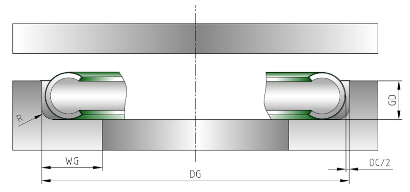
CSI: Internal pressure, spring energised
024563 = 245,63 mm for groove OD = 246,19 mm The seal diameter is always the outside diameter without plating. DSO = DG – DC – (plating thickness X 2) See figure below DSO = 246,19 – 0,46 – 2 X 0,05 = 245,63 mm
Select the proper axial section (AS) in the table, then select the material code “M or H” based on the desired spring load.
The first digit designates the C-Ring material, the second specifies the spring material.

1: Work hardened
Plating code “S” = Silver plating Plating thickness “50” = 30 to 50 µ


If you would rather contact us directly rather than email: Please call: +44 (0) 1384 413 058
External Pressure
C Ring External
- Medium to high load
- Medium to high leak tightness
- Medium spring back
- Available in shaped seal

Please see tabs below to understand the information in this example.
CE: External pressure, system pressure energised.
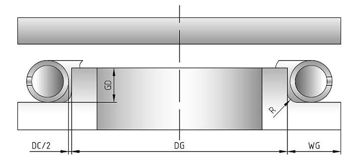
056688 = 566,88 mm for groove ID = 566,27 mm The seal diameter is always the inside diameter without plating. DSI = DG + DC + (plating thickness X 2) See figure below DSI = 566,27+ 0,51+ 2 X 0,05 = 566,88 mm
Select the proper axial section (AS) in the table, then select the material code “M or H” based on the desired wall thickness.
The first digit designates the C-Ring material, the second is always “0” in case of a C-Ring.

2: Age hardened
Plating code “G” = Gold plating Plating thickness “50” = 30 to 50 µ

If you would rather contact us directly rather than email: Please call: +44 (0) 1384 413 058
C Ring External Spring Energised
- Medium to high load
- Medium to high leak tightness
- Medium spring back
- Available in shaped seal
- Medium to high load
- Medium to high leak tightness
- Medium spring back
- Available in shaped seal
- High load
- High leak tightness
- Low spring back
- Available in shaped seal
Please see tabs below to understand the information in this example.
CSE: External pressure, spring energised.
033534 = 335,34 mm for groove OD = 334,83 mm The seal diameter is always the inside diameter without plating. DSI = DG + DC + (plating thickness X 2) See figure below DSI = 334,83 + 0,41 + 2 X 0,05 = 335,34 mm
Select the proper cross section or axial section (AS) in the table, then select the material code “M or H” based on the desired spring load.
The first digit designates the C-Ring material, the second specifies the spring material.

1: Work hardened
Plating code “N” = Nickel plating Plating thickness “50” = 30 to 50 µ


If you would rather contact us directly rather than email: Please call: +44 (0) 1384 413 058